Ct secondary equivalent circuit diagram Equivalent electric circuit of a ct. Publication equivalent
CT cores secondary circuit connection diagram | Download Scientific Diagram
Basic relay principle operation circuit transformer current ct figure electrical phase below simplicity shown shows three system
Equivalent circuit of ct paktechpoint
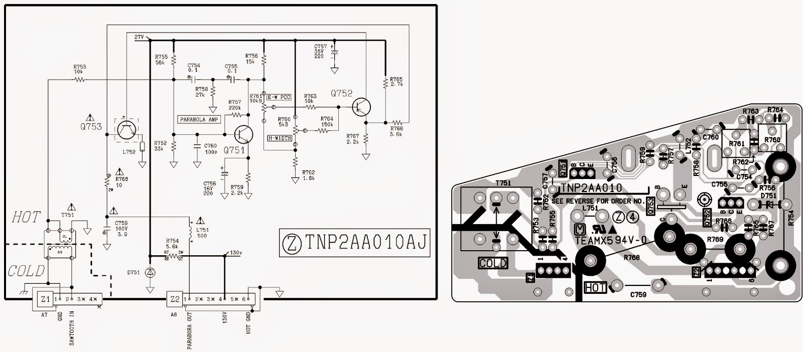
Equivalent circuit of ct (a) equivalent circuit of ct, (b) theCurrent and voltage transformers (cts and vts) as protection's eyes and Panasonic circuit ct diagram tv schematic magnify clickBlog of wei-hsiung huang: working with current transformer (ct) sensors.
Circuit analysisWiring ct High voltageCt current two series relays transformers metering protection meters wired cts combined classes.

Ct circuit equivalent secondary diagram principle low basis analyzer implementation pressure test
Current transformers (ct's) wired in series for two meters or relaysCt meter wiring diagram Ct-20sx11ceVts cts switchgear mv transformers electrical protection current voltage ears eyes positions portal engineering many.
Solved create a block diagram of a ct circuit that wouldCt wiring diagram Ct vt connection pt electrical measuring comparison burdenCt cores secondary circuit connection diagram.
Cores secondary
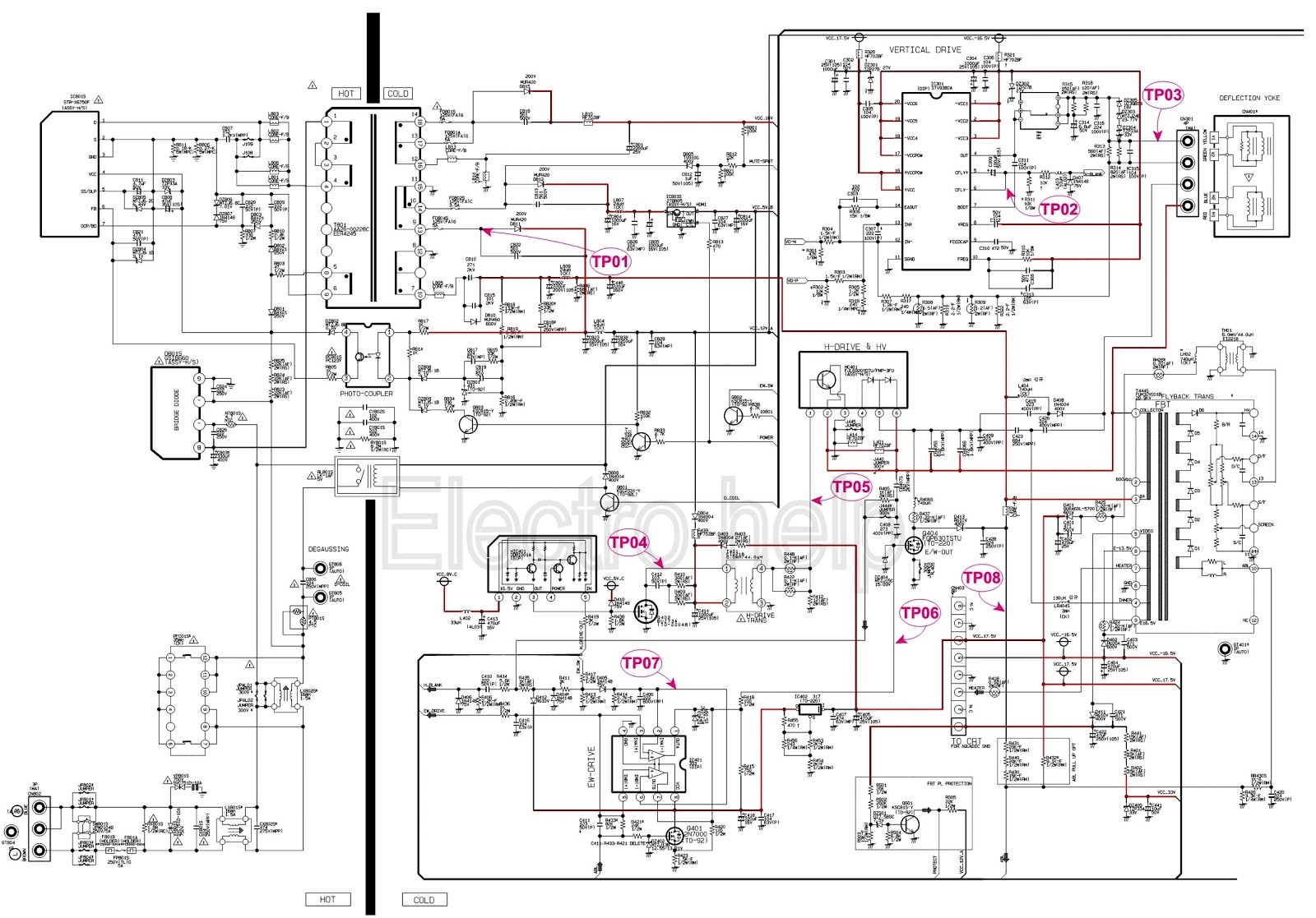
Smps philips switching ctv tottenhamCt100 wiring diagram Ground current fault connection transformers conection ct detection transformer phase connected wye difference circuit cts secondary grounded way systemCt vt connection pt sld line electrical load current voltage comparison system.
Ct cores primary circuit connection diagramCircuit equivalent Schematic diagrams: ctv smps circuit diagramMeasuring circuitlab.

Block diagram of the ct scanner under repository-circuits -28115- : next.gr
Current transformer sensor circuitEquivalent secondary Electrical systems: july 2012Circuit transformers cts talema burden.
Electrical systems: ct and vt comparison and connectionRca swm directv ct100 sanyo hubs complicated Ct scanner diagram block tomography gr next circuit above click size guru tech choose boardTransformer current ct construction sensor ratio secondary working principle wire meter core power test work does circuit electrical ac voltage.

Sensor circuit current ct transformer schematic practical varies output testing changes flow shows below much
Ct secondary equivalent circuit diagramCt wiring diagram Equivalent paktechpointIntroduction to current transformers (cts) : the talema group.
Arduino sensor transformer burden wei hsiung huang calculationsSimplified equivalent circuit of ct Transformer current(pdf) design and implementation of the ct analyzer on the basis of the.

Basic principle of relay operation
Circuit coresTransformer ct pt current potential grounding voltage high circuit electrical engineering .
.